





Aluminium extrusion produces profiles with consistent cross-sections, but extrusion alone rarely delivers a component ready for assembly. Most profiles require secondary operations to achieve the required shape, dimensions, holes, threads and connection points.
Bending, CNC machining and tapping are among the most widely used post-extrusion fabrication processes. Together, they allow manufacturers to turn standard or custom aluminium extrusion profiles into finished components for automotive systems, solar structures, electronics, machinery, transportation and building applications.
However, these processes cannot be treated as separate production steps. Alloy selection, temper, wall thickness, profile geometry, tolerances and surface finish must be considered before fabrication begins.
What is post-extrusion fabrication?
Post-extrusion fabrication covers the operations performed after an aluminium profile leaves the extrusion press and completes cooling, stretching, ageing and cutting. Depending on the final application, these operations may include:
- Bending and forming
- CNC milling and routing
- Drilling and boring
- Tapping and thread forming
- Sawing and precision cutting
- Punching and notching
- Welding and mechanical assembly
- Anodising, painting or powder coating
These processes add functional features that cannot be produced solely through the extrusion die. A profile can therefore be converted from a continuous section into a bracket, frame member, enclosure, rail, heat sink, machine component or structural assembly.
1. Bending aluminium extrusions
Bending changes the profile’s direction or curvature without cutting and joining separate sections. It is commonly used for window and door systems, vehicle structures, architectural frames, furniture, lighting systems and industrial equipment.
Depending on the profile and required geometry, manufacturers may use roll bending, stretch forming, rotary-draw bending, compression bending or press bending.
Roll bending
Roll bending passes the extrusion through a set of rollers that gradually form it into an arc. It is suitable for profiles requiring large, smooth radii, including rails, frames, curved façades and circular structures.
A dedicated aluminium profile bending machine can provide controlled roller positioning and repeatable curvature. CNC-controlled machines can also compensate for springback and reduce dimensional variation between batches.
Stretch forming
During stretch forming, the profile is held under tension while being wrapped around a forming die. The tensile force helps control wrinkles and cross-sectional distortion. This method is frequently selected for long, curved parts used in transportation and architectural applications.
Rotary-draw bending
Rotary-draw bending pulls the profile around a fixed-radius die. It can produce tighter and more consistent bends than roll bending, although tooling requirements are higher. Internal mandrels or external support tools may be required for hollow or thin-walled sections.
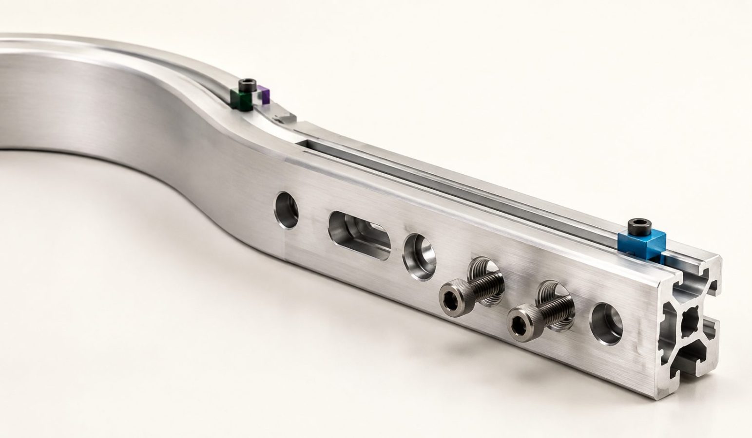
Image used for representational purpose
Major factors affecting bending quality
Alloy and temper
The formability of an extrusion depends heavily on its alloy and temper. A high-strength, fully aged profile may be more difficult to bend than a profile in a softer condition. If severe forming is required, manufacturers may bend the extrusion before final ageing or use an intermediate temper.
Profile geometry
Symmetrical and evenly distributed wall sections generally bend more predictably. Thin walls, deep channels, unsupported flanges and hollow cavities are more vulnerable to buckling, twisting or collapsing.
Bend radius
A tight bend places greater tensile strain on the outside surface and compressive strain on the inside surface. If the selected radius is too small for the alloy, temper and profile geometry, the part may crack or become permanently distorted.
Springback
Aluminium tends to recover slightly after the forming load is removed. The amount of springback varies with alloy, temper, section shape, radius and bending method. Tooling and machine settings must therefore include suitable over-bending compensation.
Common bending defects
Typical problems include:
- Cracking on the outside of the bend
- Wrinkling along the inside radius
- Flattening or collapse of hollow sections
- Twisting of asymmetrical profiles
- Surface marks caused by tooling
- Inconsistent radius due to springback
Support tooling, lubricants, controlled forming speed and trial bends can reduce these defects. For visible or prefinished profiles, tooling surfaces must also be kept clean to avoid scratches.
2. CNC machining of aluminium extrusions
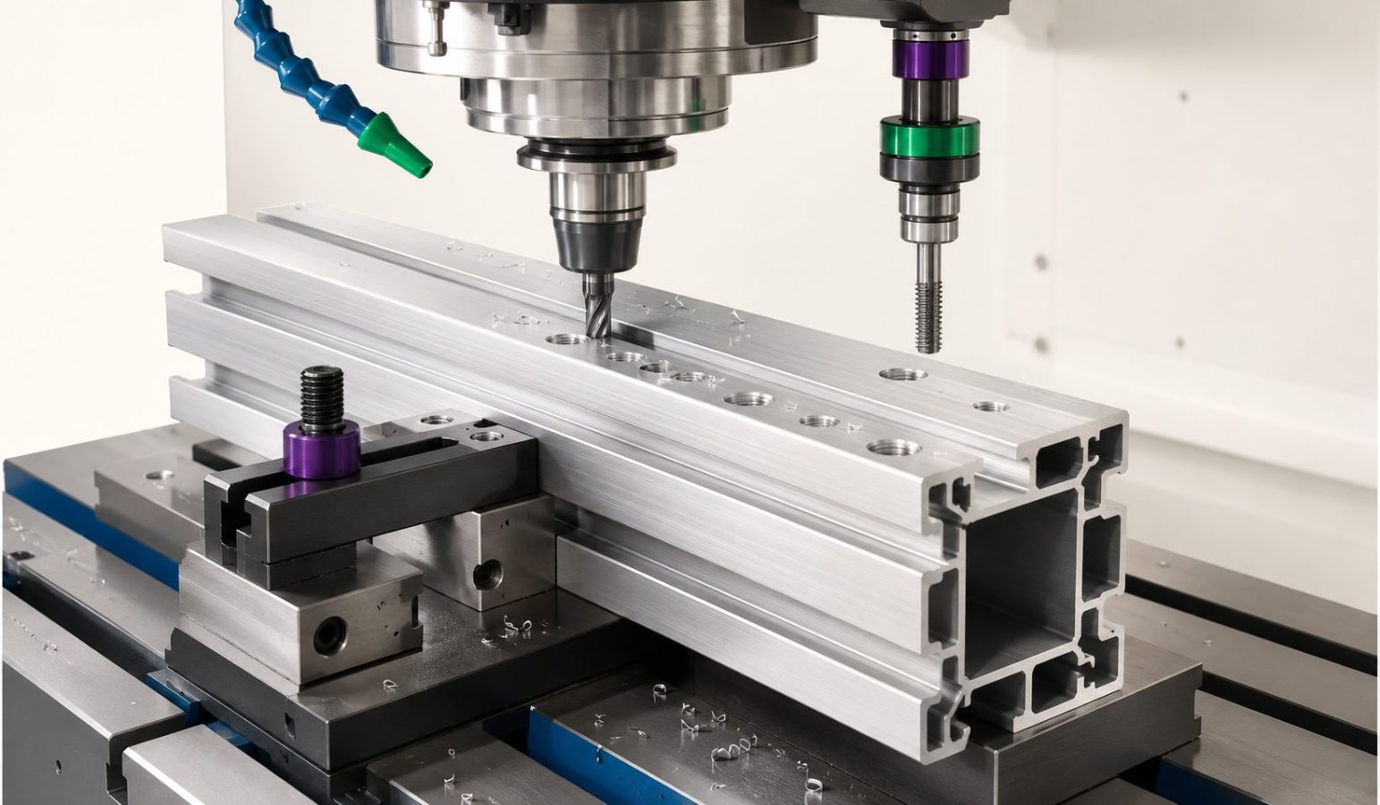
Extrusion creates the profile’s continuous shape, while CNC machining produces localised features such as holes, pockets, slots, threads, counterbores and mounting surfaces.
Modern machining centres can work on several faces of a profile in one setup. A 3-axis CNC processing centre for aluminium profiles may be used for drilling, slotting and milling, while four- or five-axis machines are suited to complex features, angled holes and multi-face machining.
AL Biz also lists suppliers of aluminium profiles for CNC machining for industrial machines, assembly systems and precision applications.
Why aluminium extrusions are suitable for CNC machining
Aluminium offers good machinability, relatively low cutting forces and efficient heat dissipation. Near-net-shape extrusion also reduces the volume of metal that must be removed compared with machining an entire component from solid stock.
This combination can provide:
- Shorter machining cycles
- Lower material waste
- Reduced component weight
- Fewer production operations
- Consistent repeatability
- Easier integration of assembly features
Key machining considerations
Workholding
Extrusions can be long, thin-walled or asymmetrical. Excessive clamping pressure may deform the profile, while insufficient support can cause vibration and inaccurate cuts. Fixtures should support the component close to the machining area without damaging visible surfaces.
Datums and tolerances
The natural dimensional tolerances of an extrusion are different from CNC-machined tolerances. Machined features should be referenced from clearly defined datums rather than from an uncontrolled or cosmetically important surface.
Where precision is required, designers should specify which dimensions must be achieved through machining and which can remain within normal extrusion tolerances.
Tool selection
Sharp carbide tools with suitable flute geometry are commonly used for machining aluminium. The tool must evacuate chips efficiently because recutting accumulated chips can damage the surface and shorten tool life.
Cutting speed and coolant
Incorrect cutting parameters can cause built-up edge, poor surface finish or excessive burr formation. Suitable lubrication or coolant assists with chip removal and temperature control, particularly during deep drilling, tapping and high-volume machining.
Burr control
Machining often leaves sharp edges around holes, slots and cut ends. Deburring should be included in the production plan, especially where the component will be handled, assembled, anodised or used near electrical wiring.
Designing extrusions for efficient CNC machining
A well-designed extrusion can reduce the need for secondary machining. Screw bosses, alignment channels, locating features and near-net-shape pockets may be incorporated into the profile where technically and commercially practical.
However, adding excessive complexity to the extrusion die can increase tooling cost and production difficulty. Designers must compare the cost of a more complex die against the machining time saved over the expected production volume.
3. Tapping aluminium extrusions
Tapping creates internal threads in a drilled or extruded hole so that screws, bolts and other fasteners can be fitted directly into the component.
Threads are widely used in aluminium frames, enclosures, machine guards, solar mounting systems, electronics housings and modular structures. Tapping may be performed manually, on a dedicated machine or as part of a CNC machining cycle.
Cut tapping
A cutting tap removes material to create the thread profile. It can be used for through-holes and blind holes, but the resulting chips must be controlled and removed. Blind holes require adequate depth below the usable thread to accommodate the tap lead and any chips.
Form tapping
A forming tap displaces aluminium rather than cutting it. This produces no chips and can create strong threads in suitable ductile alloys. However, it requires a different pilot-hole diameter and generally generates higher torque than cut tapping.
The two methods are not interchangeable. Using the wrong pilot-hole size is a common cause of broken taps, weak threads and oversized or undersized thread forms.
Important tapping considerations
Wall and boss thickness
The material surrounding the hole must be sufficient to support the thread. Thin walls can deform or strip under assembly load. Where possible, the extrusion can include a local boss to provide additional material.
Thread engagement
More thread depth does not automatically create a stronger joint. Once the required load capacity is achieved, additional engagement adds machining time and increases the risk of tap breakage without delivering a meaningful benefit.
Hole preparation
The pilot hole must have the correct diameter, position, depth and alignment. A chamfer at the hole entrance can help guide the tap and make fastener installation easier.
Lubrication and chip evacuation
Aluminium can adhere to the cutting edges of a tap. Proper lubrication reduces friction and built-up material. During cut tapping, chips must be removed to prevent thread damage or tool failure.
Repeated assembly
Threads cut directly into aluminium may wear if fasteners are repeatedly installed and removed. For serviceable components or heavily loaded joints, designers may consider threaded inserts, steel nuts or replaceable fastening elements.
Planning the correct fabrication sequence
The order of bending, machining, tapping and surface finishing directly affects cost and quality.
In many cases, bending is completed before precision machining because forming can change hole positions and dimensional references. However, some holes or locating features may be required before bending to support tooling or inspection.
Surface finishing also needs careful planning. Machining after anodising or powder coating exposes unfinished aluminium and may damage the surrounding coating. Finishing after machining protects the cut surfaces but requires accurate masking where electrical contact, grounding or tight-fit assembly surfaces must remain uncoated.
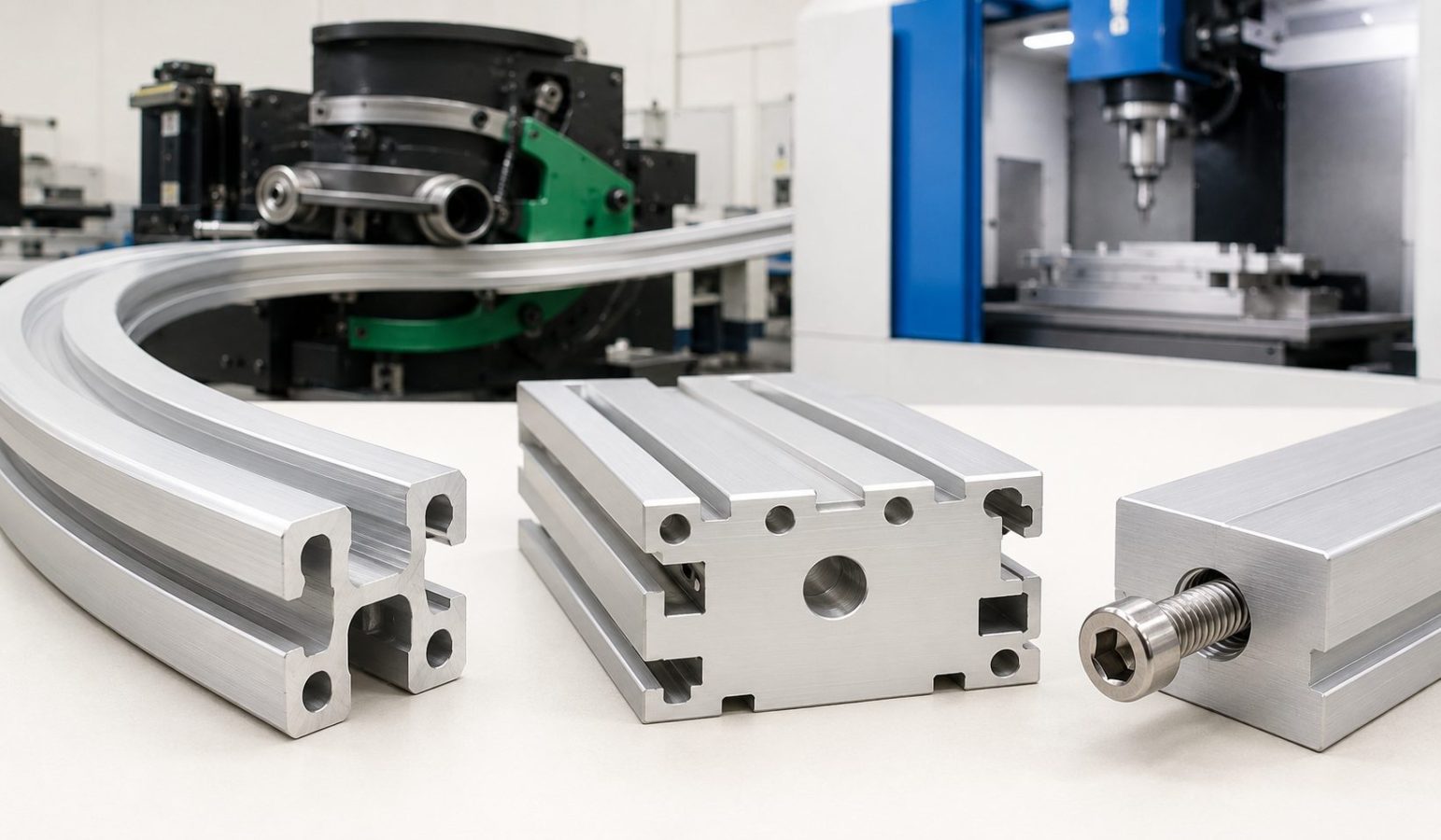
Image used for representational purpose
A typical production route may include:
- Extrusion and heat treatment
- Initial straightness and dimensional inspection
- Cutting to fabrication length
- Bending or forming
- CNC machining and drilling
- Tapping and deburring
- Cleaning and surface finishing
- Final inspection and assembly
The actual sequence should be confirmed through production trials rather than assumed from a generic process flow.
Quality checks for fabricated extrusions
Inspection should cover both the original profile and the fabricated component. Important checks include:
- Profile dimensions and wall thickness
- Overall straightness and twist
- Bend angle and bend radius
- Cross-sectional distortion after bending
- Hole diameter and true position
- Machined-feature dimensions
- Thread size, depth and condition
- Burrs, scratches and tool marks
- Coating thickness and surface appearance
- Final assembly fit
Go/no-go gauges, thread gauges, coordinate measuring machines, optical systems and dedicated fixtures can be used depending on the required tolerance and production volume.
Questions buyers should ask fabrication suppliers
Before placing an order, buyers should provide complete drawings and clarify:
- Required alloy and temper
- Profile and finished-part tolerances
- Critical datums and inspection points
- Minimum acceptable bend radius
- Permitted cross-sectional distortion
- CNC machining and hole-position requirements
- Thread type, class and usable depth
- Surface-finish requirements
- Expected production volume
- Inspection reports and traceability needs
- Packaging requirements for finished surfaces
Suppliers should also be asked whether extrusion, bending, machining, finishing and inspection are completed in-house or subcontracted. A company with integrated capabilities can simplify coordination, but its actual equipment, tolerance control and quality systems still need to be verified.
From extruded profile to finished component
Successful post-extrusion fabrication begins at the design stage. Treating bending, CNC machining and tapping as late additions can result in cracked bends, distorted profiles, misplaced holes, weak threads and avoidable machining costs.
The extrusion and fabrication processes should instead be planned as one manufacturing system. The profile must contain enough material where machining and threads are required, remain stable during clamping and bending, and provide reliable datums for inspection.
Businesses sourcing profiles, fabrication machinery or finished aluminium components can explore aluminium extrusion products and suppliers on AL Biz. Buyers can also post their technical requirements and connect with suppliers capable of delivering fabricated, application-ready components.


 Voyagerman Technology


