





The core concept of molten aluminium refining
Molten metal refining is fundamentally a thermodynamic selection problem, not a filtration problem. Every impurity dissolved in a melt is a distinct chemical species and each one has its own reactivity, vapour pressure, and solidification behaviour relative to the base metal. Refining works by exploiting a difference between the base metal and the impurity along one of a small number of physical or chemical axes and it fails when no such exploitable difference exists.
For selective oxidation or chlorination to work, the impurity metal M must be thermodynamically more reactive than the base metal; that is, its oxide or chloride must be more stable (more negative free energy of formation) than the base metal’s own oxide or chloride. This is the same logic captured in an Ellingham diagram: Elements whose oxide-formation line sits below the base metal’s line will oxidise preferentially and can be skimmed off; elements whose line sits above it will not react and will remain in solution no matter how much oxidant or chlorine is added.
Al + (3/n) MXn → AlX3 + (3/n) M (X = O or Cl)
If M is more reactive than aluminium (sodium, calcium, magnesium, lithium), this reaction runs in the direction that oxidizes/chlorinates M and leaves aluminium metallic, which is exactly the chemistry demagging relies on. If M is less reactive than aluminium (iron, copper, manganese, zinc, silicon), the reaction cannot run in that direction under normal conditions: Adding more chlorine or more oxidising flux does not touch these elements; it simply starts attacking the aluminium itself once the reactive impurities are exhausted.
This is the single most important practical consequence for a recycling or refining operation: Reactivity-based treatment (chlorine gas, fluoride/chloride fluxes, oxidative fluxing) only ever removes the reactive-metal group (Na, Ca, Mg, Li) and, to a lesser extent, hydrogen and certain inclusion-forming compounds. It does not affect whatsoever on Fe, Cu, Mn, Si, or Zn.
Demagging
Magnesium is a deliberate alloying element in several wrought alloy families (notably the 5xxx series), but post-consumer scrap frequently carries more Mg than the target alloy allows. Because magnesium has a strong affinity for oxygen and does not passively separate from the melt, it must be actively stripped to bring the melt within specification before casting.
Demagging (“de-magnesiation”) is the removal of excess magnesium from molten aluminium before casting to reach the desired final composition. It is encountered predominantly in secondary (recycling) operations, particularly when processing used beverage can (UBC) scrap or other high-magnesium content mixed scrap streams.
The process mechanism
- The most common industrial method is chlorine gas injection, typically diluted with an inert carrier gas (nitrogen or argon) for safety and dosing control.
- Flux-based demagging using chloride/fluoride salt mixtures, which is less gas-intensive, but generates more dross
- Aluminium fluoride (AlF₃) addition as (Potassium Aluminium Fluoride), reacting with Mg to form MgF₂, used where chlorine handling is restricted
When chlorine gas is injected into aluminium-containing magnesium, the reaction does not proceed as a single-step direct attack of Cl₂ on dissolved Mg. Instead, it proceeds through an aluminium chloride intermediate, because chlorine first encounters the overwhelming excess of aluminium at the bubble surface:
- Chlorine reacts with aluminium at the bubble–melt interface, forming aluminium trichloride:
2 Al + 3 Cl₂ → 2 AlCl₃ (g)
- Because magnesium is thermodynamically more reactive than aluminium, the AlCl₃ formed immediately reacts with dissolved magnesium in an exchange reaction, regenerating aluminium and producing magnesium chloride:
2 AlCl₃ + 3 Mg → 3 MgCl₂ + 2 Al
- MgCl₂ has low density relative to the melt and reports to the dross/slag layer, where it is separated. If sodium is also present, a further exchange reaction can occur, since sodium is even more reactive toward chlorine than magnesium:
MgCl₂ + 2 Na → 2 NaCl + Mg
This cascading exchange sequence — Al → AlCl₃ → Mg → MgCl₂
It explains an important practical feature of chlorine refining: The rate at which MgCl₂ forms is governed by the bubble surface area (where the AlCl₃ intermediate is generated), while the rate of any subsequent sodium removal is governed by the contact area between the MgCl₂-bearing phase and the melt, which is a different, second-stage mass-transfer step. This is also the source of the aluminium chloride fume problem: Any AlCl₃ that reaches the melt surface without first reacting with Mg escapes as gas and reacts with atmospheric moisture to form Al₂O₃ dust and HCl, which is the basis of the workplace-hygiene and environmental concerns associated with chlorine-based demagging.
KPIs of demagging process
| Parameter | Purpose |
| Melt sampling frequency (spectrometer) | Real-time tracking of Mg ppm/wt% reduction during treatment |
| Chlorine consumption (kg Cl₂/t) | Cost and reagent efficiency metric |
| Off-gas treatment (HCl/Cl₂ scrubbing) | Mandatory for environmental and safety compliance |
| Dross generation rate | Demagging increases dross output; tracked for metal yield impact |
| Reaction / holding time | Time in furnace before tap, sized to reach target Mg level |
Table 1: KPIs of demagging process
Demagging capability is often the deciding factor in whether a mixed-scrap recycling plant can produce clean, wrought-alloy-compliant output (e.g., 3xxx/5xxx series) rather than being limited to lower-value casting alloys. It requires dedicated infrastructure, chlorine handling and storage, injection systems, special safety devices, operational skills and off-gas scrubbing and represents a distinguishing capex/opex line item in plant business plans and process design, since it adds both capital cost and tighter operational control requirements compared with simple remelting.
Metallic magnesium production methods
Magnesium always appears in nature in ionic form with the following electron arrangement: 1S22S22P63S2. This arrangement is characterised by the low ionisation energies relative to the two most external electrons, which are at the 3S level. This is the reason why univalent or trivalent magnesium is not found in nature, only bivalent. The low standard reduction potential of magnesium is the reason why no metallic magnesium is found in nature.
Mg2+ + 2e– = Mg E0 = -2.375V
All production technologies, therefore, require a reduction agent that can transfer two electrons to magnesium. Theoretically, the reduction agents are electric current operated at the appropriate potential, carbon in various forms (mostly coal), silicon-based materials (FeSi), CaC2 and aluminium.
Primary magnesium is extracted mainly through two fundamental categories of production: Electrolytic processes and thermal reduction processes.
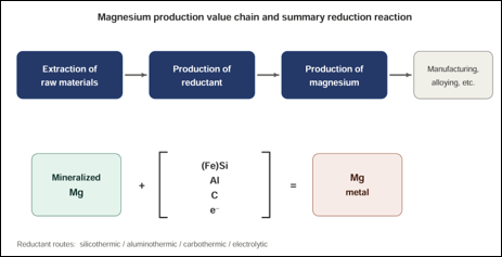
Figure 1: Magnesium production methods
Electrolytic processes: Hydrochloric acid leaching to produce magnesium chloride solution, followed by thermal hydrolysis or electrolysis to produce magnesium. The electrolytic process, or hydrometallurgical process, is mainly used to produce magnesium from carnallite, salt brines, and seawater. In this process, magnesium chloride (MgCl2) is extracted, dried, melted and reduced in a direct current electrolytic cell to produce magnesium. The carbon intensity of the electrolysis of magnesium is highly dependent upon the source of electricity, and utilising greater sources of renewable energy results in reduced carbon emissions.
Thermal reduction processes: Unlike aluminium, magnesium is volatile at relatively low temperatures. This physical property, which produces its greater inflammability, also offers possibilities of direct reduction that are not available with aluminium. In the basic reaction:
MgO + X = XO + Mg
If X is nonvolatile, the reaction may be forced to the right at high temperatures by the evolution of magnesium vapour, despite the large negative value of the heat of reaction, which is almost bound to follow the use of any available commercial reducing agent.
| 1 bar | 1 mbar | 1 bar | 1 mbar | |
| Silicon | 2143 ⁰C | 1325 ⁰C | 2489 ⁰C | 1318 ⁰C |
| Aluminium | 1475 ⁰C | 850 ⁰C | 1427 ⁰C | 842 ⁰C |
| Ferro Silicon | 1789 ⁰C | 1155 ⁰C | 1870 ⁰C | 1098 ⁰C |
| Calcium Carbide | 1847 ⁰C | 1200 ⁰C | 1828 ⁰C | 1091 ⁰C |
Table 2: Minimum reduction temperatures of calcined dolomite at 1 bar & 1 mbar for different reductants
The selection of reductants is a major factor in the determination of the optimum operation and production of optimum/valuable by-products of the metallothermic process. The reductant, together with the magnesium feed material and required additives, determines the slag melting temperature and subsequent minimum operating temperature, valuable by-products production, acceptable range of carbon emissions, and ultimately the magnesium metal production rate.
Traditionally, ferrosilicon alloy is the main reductant for economic reasons. However, thermodynamic data suggest that aluminium or aluminium alloys may be more efficient.
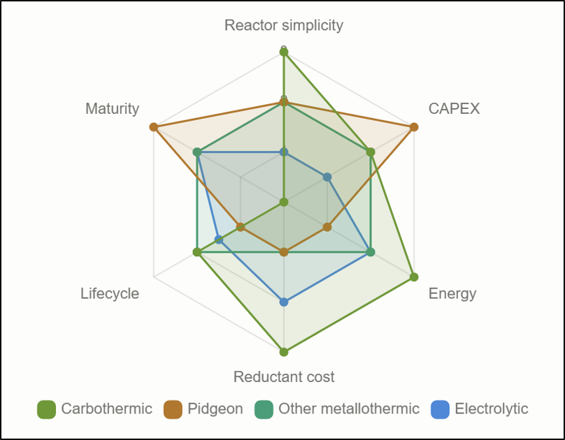
Figure 2: Comparison of primary magnesium production methods
Energy and carbon cost of primary magnesium production
Primary magnesium is produced almost entirely (~85–88% globally) in China using the Pidgeon (silicothermic) process, a thermal-reduction batch process that is by far the most energy- and carbon-intensive commercial route. A smaller share comes from electrolytic production (Israel, China’s Qinghai region) and modified silicothermic processes (e.g., Brazil’s RIMA/Bolzano process, Turkey’s KAR plant).
Energy consumption by process step: Pidgeon process, China
China, 2019 average (plus KAR plant, Turkey, 2014 for comparison). Source: DLR/IMA 2020 Carbon Footprint LCA Study.
Total energy = fuel gas (varies by which gas is used at the plant) + electricity. Figures in MJ per tonne Mg.
| Process step | Coke oven gas (2019) | Semi-coke oven gas (2019) | Producer gas (2019) | Natural gas (2019) | KAR plant, Turkey (2014) |
| Calcination | 22,324 | 48,299 | 27,023 | 27,811 | 48,581 |
| Briquetting | 806 | 806 | 806 | 806 | 1,620 |
| Reduction | 51,142 | 55,021 | 43,902 | 46,050 | 51,287 |
| Refining | 8,639 | 8,200 | 4,786 | 4,494 | 2,880 |
| Total | 82,912 | 112,326 | 76,518 | 79,161 | 104,368 |
Table 3: Energy consumption by process step: Pidgeon process, China
That’s roughly 77–112 GJ (21–31 MWh) per tonne of magnesium, depending on which fuel gas the plant uses — down from 84–133 GJ/t in 2011.
Electricity alone (2019, all fuel-gas types combined) totals about 1,230 kWh/t Mg, split roughly: calcination 300, briquetting 220, reduction 580, refining 130 kWh/t.
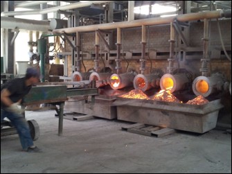
Figure 3: Chinese horizontal Pidgeon reduction furnace
Carbon emissions: Pidgeon process, China
Cradle-to-gate carbon footprint by scope and life-cycle stage. Source: DLR/IMA 2020 Carbon Footprint LCA Study; IMA/Tauber decarbonization roadmap (2024).
| Scope | Emissions |
| Ferrosilicon input (upstream) | 12.5 kg CO2e/kg Mg |
| Calcination | 6.7–9.1 kg CO2e/kg Mg (varies by fuel) |
| Pidgeon process itself (calcination + reduction + refining, excl. upstream) — weighted average | 12.1 kg CO2e/kg Mg (down from 13.4 in 2011) |
| — of which: Calcination | 7.9 kg CO2e/kg Mg |
| — of which: Reduction | 3.7 kg CO2e/kg Mg |
| — of which: Refining | 0.5 kg CO2e/kg Mg |
| Full cradle-to-gate, weighted China average (2019/2020 LCA study) | 21.8 kg CO2e/kg Mg |
| By fuel type (unweighted range) | 19.3 (semi-coke oven gas) to 28.4 (producer gas) kg CO2e/kg Mg |
| 2011 baseline (for comparison) | ~30 kg CO2e/kg Mg |
| Tauber/IMA roadmap (2024), “China average” | 21.8 kg CO2e/kg Mg; “world average” 21.3 |
| Turkey (KAR plant, Pidgeon variant with solar) | ~20 kg CO2e/kg Mg |
Table 4: Carbon emissions: China Pidgeon process
For context, global average aluminium production runs about 18 kg CO2e/kg (Europe average ~8.7), so the Chinese Pidgeon process is often cited as running higher than average primary aluminium on a per-kg basis; though magnesium’s ~35% weight advantage over aluminium partly offsets this over a component’s life.
| Process/source | Energy (per t Mg) | Carbon footprint (kg CO2e/kg Mg) |
| Pidgeon, China, weighted average (2019/2020) | ~77–112 GJ fuel gas + ~1,230 kWh electricity | 21.8 (full cradle-to-gate); 12.1 (process only) |
| Pidgeon, China, world average cited by IMA (2024) | not stated | 21.3–21.8 |
| Pidgeon variant, KAR, Turkey | not stated | ~20 |
| Silicothermic (Bolzano), RIMA, Brazil | not stated | 10.1 (2020) → 5.76 (2023) |
| Electrolytic, Dead Sea Magnesium, Israel | not stated | 17.8 (no credit) / 14.0 (credit) / 7.07 (2023 update) |
| Electrolytic, Qinghai/QSLM, China | not stated | 8.5 (gross) / 5.3 (net) / 4.6 (2025, lowest tracked) |
| Alliance Magnesium (project), Canada | not stated | <5 |
| Latrobe Magnesium (pilot), Australia | not stated | 1.5–10.2, feedstock-dependent |
| Verde Magnesium (pilot), Romania (ALT/aluminothermic) | not stated (relative indices only) | <3 confirmed; target <1 |
| Vacuum carbothermal reduction (VCTRM) | Higher than Pidgeon (hotter process, 1627K vs 1427K) — no figure given | Not reported |
| Secondary/recycled Mg, Europe (Magontec) | ~5% of primary energy | 0.38–0.45 |
| Secondary alloy, Europe (CROWN, scope 1–3) | ~5% of primary energy | 2.42 |
| IMA 2030 target for new primary projects | not stated | ~4 (average) |
Table 5: Summary of energy and carbon emissions of available and emerging/pilot stage technologies
Conclusions
- Considering both its role as an aluminium alloying element and its other applications, we need more and “green” magnesium.
- Each kilogram of magnesium removed from molten aluminium via the demagging process (assuming Chinese origin) represents the waste of both 21.3–21.8 kg of CO2e carbon emissions and approximately 79–112 MJ of embodied energy.
- One must not overlook the aluminium losses that cannot be calculated during the demagging process (depending on the demagging agent, process conditions, and process duration).
Could magnesium-based refining issues be minimised without the need for demagging to achieve the “closed-loop” goal by using a more precisely formulated charging recipe?


 Voyagerman Technology


